doi: JSVIAG 0022-460X Crossref Google Scholar and Auregan Y., “ Modelling of Sound Propagation in Non-Uniform Lined Duct Using a Multimodal Propagation Method,” Journal of Sound and Vibration, Vol. 289, Nos. 4–5, Feb. 2006, pp. 1091–1111. and Thezelais S., “ Finite/Boundary Element Assessment of a Turbofan Spliced Intake Liner at Supersonic Fan Operating Conditions,” 9th AIAA/CEAS Aeroacoustics Conference, AIAA Paper 2003-3305, May 2003. J., “ A Computational Mode-Matching Approach for Sound Propagation in Three-Dimensional Ducts with Flow,” Journal of Sound and Vibration, Vol. 315, Nos. 4–5, Sept. 2008, pp. 1103–1124. and Casalis G., “ Discontinuous Galerkin Method for Acoustic Modes Computation in Lined Ducts,” 18th AIAA/CEAS Aeroacoustics Conference, AIAA Paper 2012-2153, June 2012. M., “ Acoustic Scattering by a Spliced Turbofan Inlet Duct Liner at Supersonic Fan Speeds,” Journal of Sound and Vibration, Vol. 292, Nos. 3–5, 2006, pp. 911–934. and Eversman W., “ Transmission in Flow Ducts with Peripherally Varying Liner,” 6th AIAA Aeroacoustics Conference, AIAA Paper 1980-1015, June 1980. Watson W., “ Noise Suppression Characteristics of Peripherally Segmented Duct Liners,” NASA TP-1904, 1981. An approximate method is also described to account for the effect of the nonlinear propagation on linear predictions of the liner performance when repairs are present.
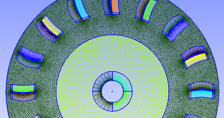
#Gmsh boundary layer fan Patch
A close agreement is demonstrated with results from an asymptotic analytical model valid for small patch widths. The effects of the extent and the location of a hard patch, representing the liner damage and repair, on the overall performance of the liner are predicted. In the current paper, the acoustic effect of damage and repair in a zero-splice liner is simulated numerically. However, damage can occur to such liners in service, and the extent to which local liner repairs reduce the effectiveness of the zero-splice design then becomes an issue. The significance of this “splice effect” has led to the adoption of “zero-splice” liners in recent turbofan nacelles. The splices scatter energy from strong rotor-locked tones into adjacent azimuthal orders for which the liner is less effective, thereby degrading the liner performance. See, for example, the Marking subdomains of a mesh demo where a pure-Python instance is used for marking boundaries.Traditional installations of turbofan intake liners include acoustically “hard” axial splices between liner segments for ease of fabrication and assembly. The compile_subdomains function produces an instance of the SubDomain class, which is a general construct used to represent criteria for taking a subset of cells.


Is that the reason I didn't get a physical.xml? I did what you said and I saw only 1 volume. I have 6 physical surfaces and 1 physical volume. xml and facet file and use the gmsh tags to represent the left and right surfaces (as in the above eg.)? So, when I import my cube from gmsh to fenics, should I just import main. left, right = compile_subdomains() < DOLFIN_EPS) & on_boundary", They create a 3D cube mesh in Fenics and classify its boundary at opposite ends (x=0 & x=1) as left and right 'subdomains' through the following statement. So, I have a question about usage of the term 'subdomain'.Īre subdomains representation of only 3D volume partitions or can they be used to represent a 2D surface/ boundary too? Is that the reason I didn't get a physical.xml? Will my 6 physical surfaces not classify as subdomains or will they be only called boundaries?


 0 kommentar(er)
